Water Level Detector EASY
An intelligent water level monitoring system with visual and audio alerts. Detects water levels and triggers alarms to prevent overflow situations.
Materials Used
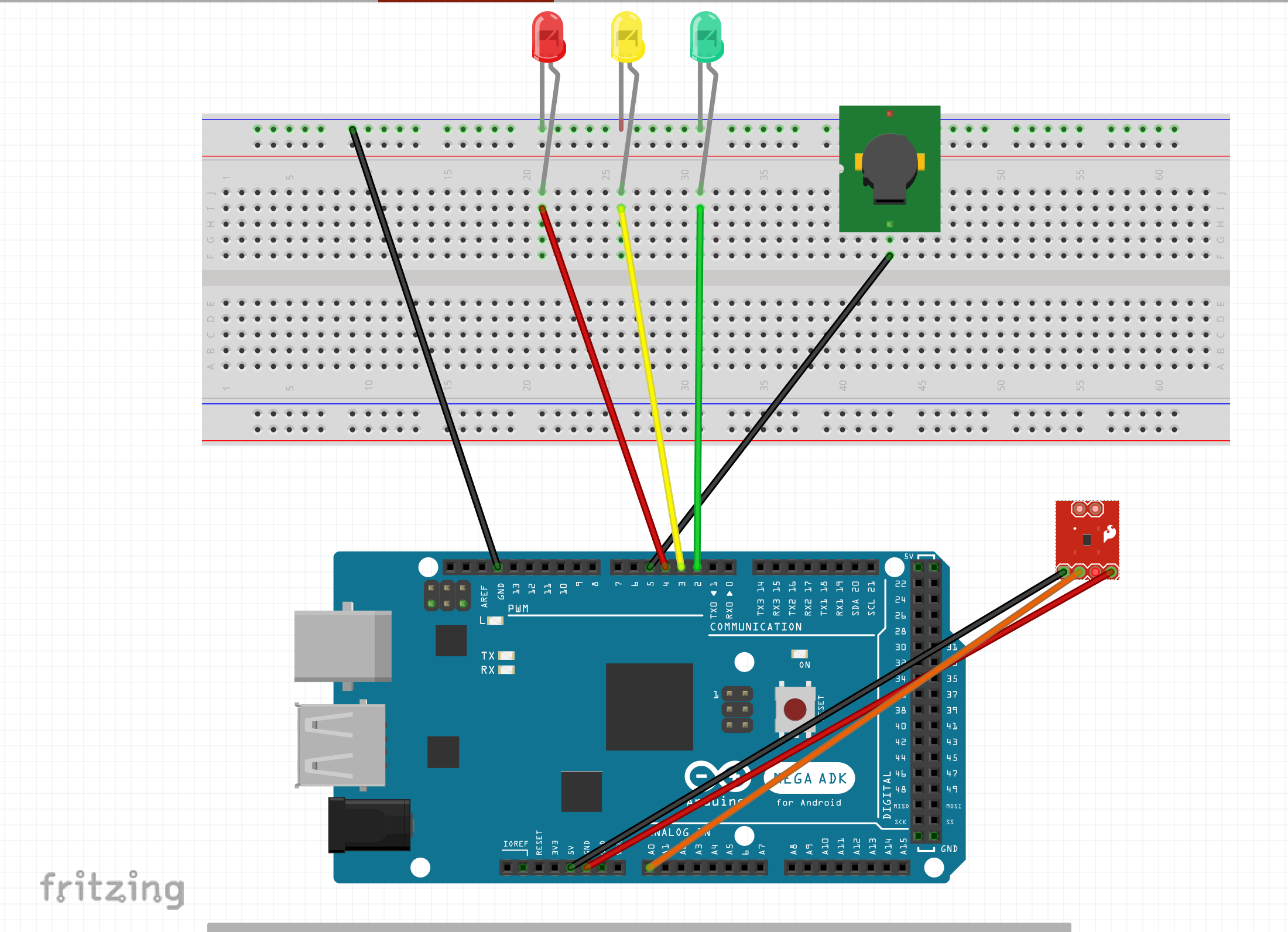
Wiring Instructions
Water Sensor: S (Signal) → A0, + → 5V, – → GND
LEDs: Green=Pin 2, Yellow=Pin 3, Red=Pin 4 (each through 220–330Ω resistor to GND)
Buzzer: + → Pin 5, – → GND
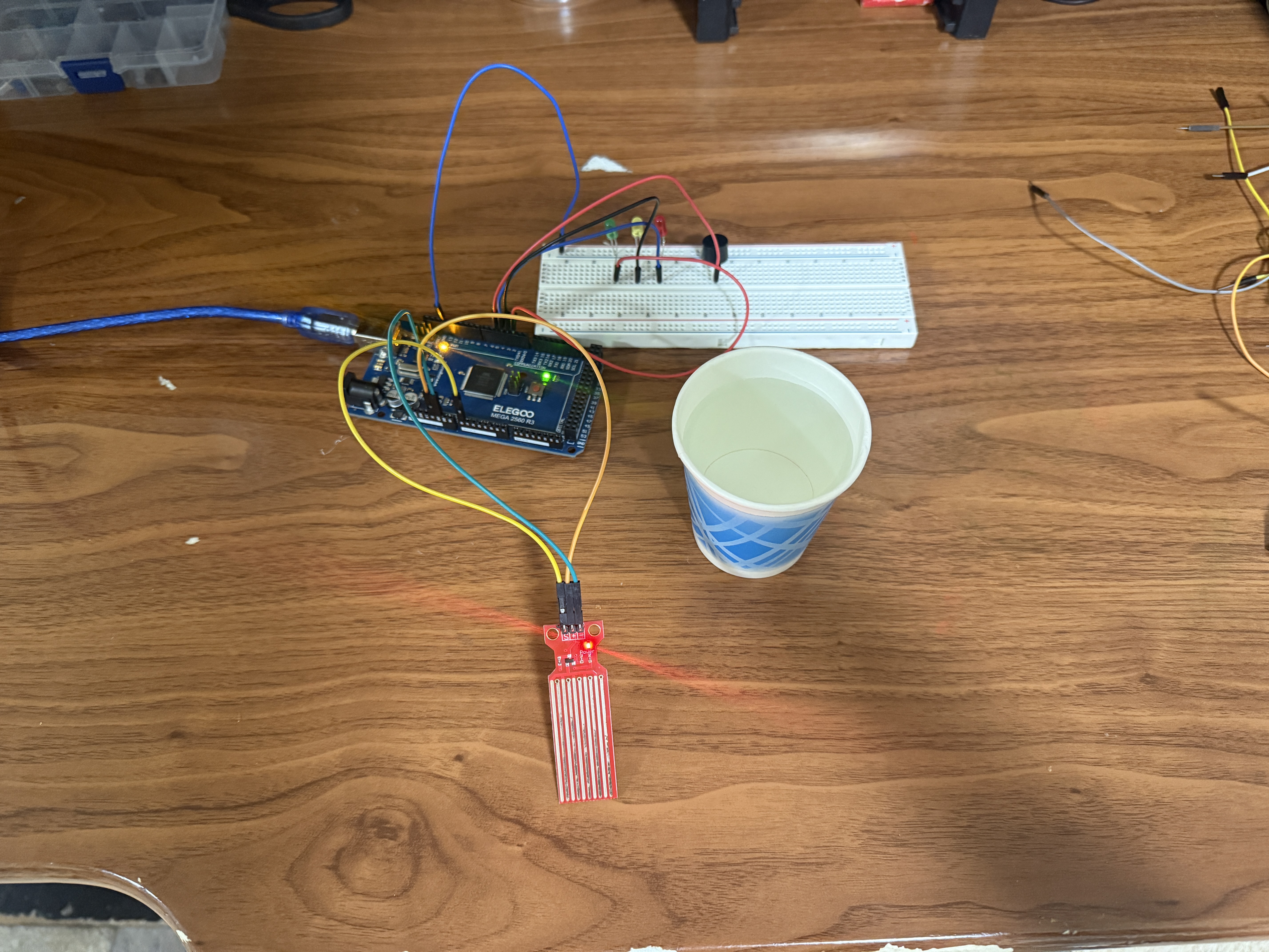
Project Photos & Demo
Arduino Code
// Water Level Detector
#include <Wire.h>
#include <LiquidCrystal_I2C.h>

LiquidCrystal_I2C lcd(0x27, 16, 2);

const int sensorPin = A0;
const int greenLED = 8;
const int yellowLED = 9;
const int redLED = 10;
const int buzzer = 11;

void setup() {
  Serial.begin(9600);
  lcd.init();
  lcd.backlight();

  pinMode(greenLED, OUTPUT);
  pinMode(yellowLED, OUTPUT);
  pinMode(redLED, OUTPUT);
  pinMode(buzzer, OUTPUT);

  lcd.setCursor(0, 0);
  lcd.print("Water Level");
  lcd.setCursor(0, 1);
  lcd.print("Detector Ready");
  delay(2000);
}

void loop() {
  int waterLevel = analogRead(sensorPin);
  int percentage = map(waterLevel, 0, 1023, 0, 100);

  lcd.clear();
  lcd.setCursor(0, 0);
  lcd.print("Water Level:");
  lcd.setCursor(0, 1);
  lcd.print(percentage);
  lcd.print(" %");

  Serial.print("Water Level: ");
  Serial.print(percentage);
  Serial.println(" %");

  // Turn off all indicators
  digitalWrite(greenLED, LOW);
  digitalWrite(yellowLED, LOW);
  digitalWrite(redLED, LOW);
  noTone(buzzer);

  if (percentage < 30) {
    // Low water level
    digitalWrite(greenLED, HIGH);
  } else if (percentage < 70) {
    // Medium water level
    digitalWrite(yellowLED, HIGH);
  } else {
    // High water level - Alert!
    digitalWrite(redLED, HIGH);
    tone(buzzer, 1000);
    delay(500);
    noTone(buzzer);
    delay(500);
  }

  delay(1000);
}
🔧 Troubleshooting
Water level sensor not responding? Here's how to fix it:
- Verify connections: S (Signal)→A0, VCC→5V, GND→GND on sensor module.
- Check Serial Monitor - sensor should read ~0 when dry, higher values when wet.
- Clean sensor contacts - corrosion or dirt can prevent proper water detection.
- Ensure water touches the sensor traces - submerge enough to complete circuit.
Water sensors corrode over time. Clean with isopropyl alcohol and dry thoroughly. For long-term use, coat sensor (not contacts) with clear nail polish to prevent corrosion.
- Check LED connections: Green→D2, Yellow→D3, Red→D4, each through 220-330Ω resistor to GND.
- Verify LED polarity - long leg to pin (through resistor), short leg to GND.
- Adjust threshold values in code (30%, 70%) to match your sensor's readings from Serial Monitor.
- Test each LED individually with digitalWrite(pin, HIGH) to confirm they work.
Open Serial Monitor, test sensor in different water levels, note the readings. Adjust percentage thresholds in code to match your actual sensor values.
- Check buzzer connection: + (longer leg)→Pin 5, - (shorter leg)→GND.
- Verify you're using tone() function: tone(buzzer, 1000) for passive buzzer, or digitalWrite for active buzzer.
- Test buzzer type - active buzzers need only HIGH/LOW, passive buzzers need tone() with frequency.
- Ensure noTone(buzzer) is called to stop sound after alert.
Active buzzer: Has built-in oscillator, simpler code (HIGH/LOW). Passive buzzer: Needs tone() function, can play different frequencies. Check datasheet if unsure!
- Verify I2C LCD connections: SDA→Pin 20/A4, SCL→Pin 21/A5, VCC→5V, GND→GND.
- Install LiquidCrystal_I2C library from Library Manager.
- Check I2C address (usually 0x27 or 0x3F) using I2C scanner sketch.
- Adjust LCD contrast with onboard potentiometer if text is invisible.
If LCD backlight is on but no text visible, adjust the small blue potentiometer on the LCD I2C module with a screwdriver until text appears clearly.
What You Learned
Electrical Engineering Applications
This project demonstrates resistive sensing, analog signal conditioning, multi-threshold monitoring systems, and alarm triggering logic. You learned about water conductivity measurement, ADC resolution and mapping, creating graduated alert levels based on sensor readings, and implementing audio-visual warning systems. These principles are fundamental in process monitoring, safety systems, and industrial instrumentation.
Broader Technology Context
Water level detection and overflow prevention systems are critical in municipal water treatment, agricultural irrigation, sump pump automation, flood warning systems, industrial tanks and reactors, aquariums, and smart home leak detection. This multi-level alert architecture extends to fuel tanks, chemical storage, battery monitoring, and any application requiring graduated warnings before critical thresholds. Understanding preventive alarm systems is essential for safety-critical embedded applications.