Button LED Control EASY
A simple project that demonstrates how to control an LED using a push button with Arduino. Perfect for beginners learning digital input and output basics.
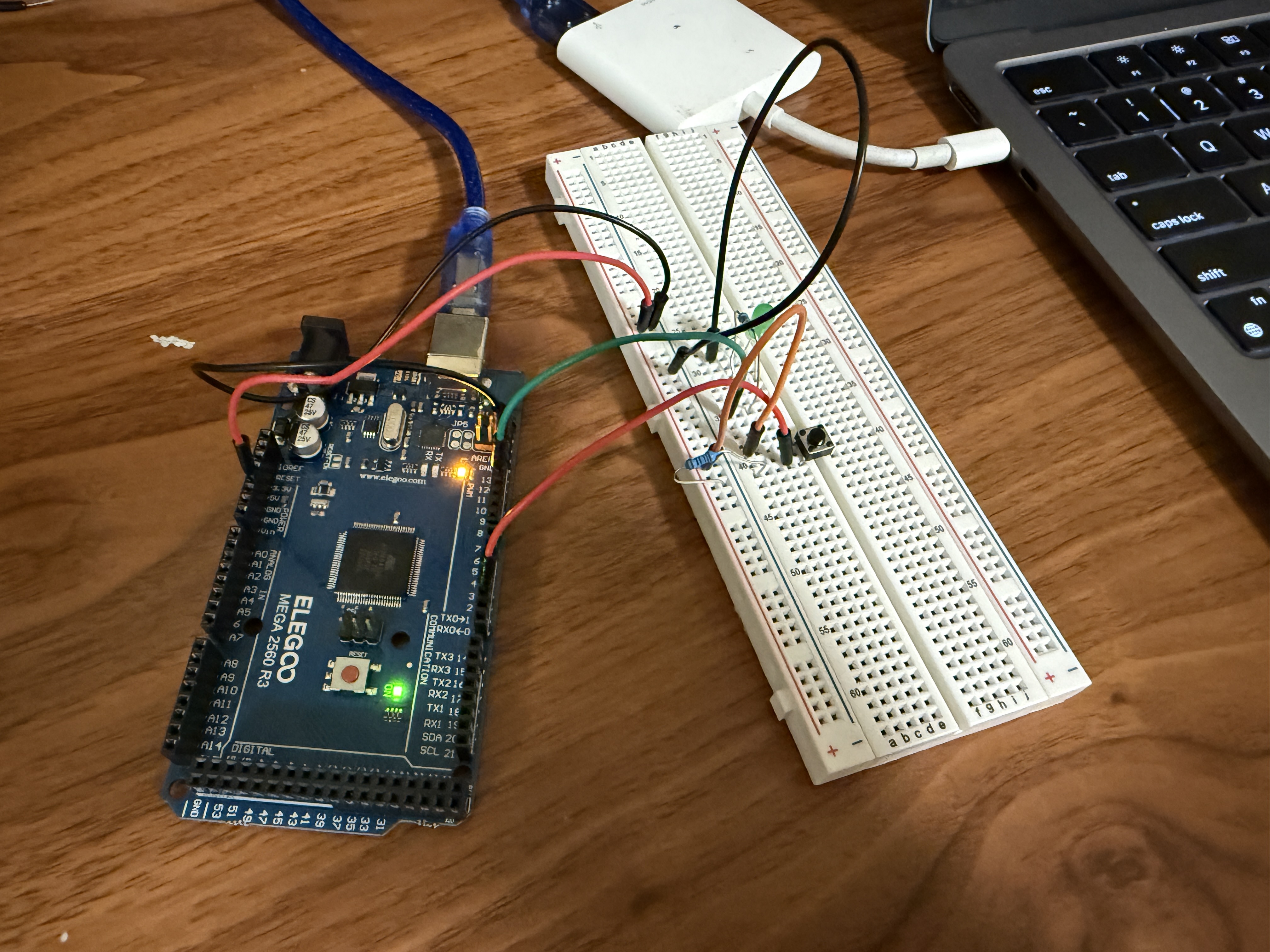
Materials Used
Wiring Instructions
Connections:
• Button leg 1 → Pin 2
• Button leg 2 → GND
• LED anode (long leg) → resistor → Pin 12
• LED cathode (short leg) → GND
Project Photos & Demo
Arduino Code
// Button-Controlled LED
const int LED_PIN = 12;
const int BUTTON_PIN = 2;

bool ledState = LOW;
bool lastButton = HIGH;

void setup() {
  pinMode(LED_PIN, OUTPUT);
  pinMode(BUTTON_PIN, INPUT_PULLUP);
  digitalWrite(LED_PIN, ledState);
  Serial.begin(9600);
}

void loop() {
  bool reading = digitalRead(BUTTON_PIN);
  if (lastButton == HIGH && reading == LOW) {
    ledState = !ledState;
    digitalWrite(LED_PIN, ledState);
    Serial.println(ledState ? "LED ON" : "LED OFF");
    delay(200); // debounce
  }
  lastButton = reading;
}
🔧 Troubleshooting
Having issues with your circuit? Check these common problems and solutions:
- Check LED polarity - the longer leg (anode) should connect to the resistor and pin 12, while the shorter leg (cathode) connects to GND.
- Verify the resistor is connected in series with the LED. Without it, the LED may burn out.
- Test with a multimeter - check if pin 12 is outputting voltage when code is uploaded.
- Try a different LED - the current one might be damaged.
If you're unsure about LED polarity, look inside the LED. The smaller piece is the positive terminal (anode), and the larger piece is negative (cathode).
- Verify the button is wired correctly - one leg to pin 2, the opposite leg to GND.
- Check that INPUT_PULLUP is used in pinMode() - this enables the internal pull-up resistor.
- Test button continuity with a multimeter when pressed to ensure it's working.
- Make sure you're connecting to opposite corners of the button (check datasheet).
Most push buttons have 4 pins but only 2 connections. Pins on the same side are always connected. Connect across the gap, not along the same side.
- Check your code logic - verify the ledState variable is toggling correctly in Serial Monitor.
- Ensure debounce delay (200ms) is present to prevent multiple rapid triggers.
- Verify digitalWrite() is called with the correct state after toggling.
- Check pin numbers match between code (pin 12) and physical wiring.
Add Serial.println() statements in your code to track button presses and LED state changes. Open Serial Monitor (9600 baud) to see real-time debugging output.
- Check for loose connections - ensure all jumper wires are firmly seated in breadboard and Arduino.
- Verify breadboard connections - make sure wires are in the correct rows.
- Increase debounce delay if LED toggles multiple times per press (try 300-500ms).
- Check power supply - weak USB power can cause erratic behavior.
Breadboard internal connections run vertically in the main area and horizontally in the power rails. Make sure you're using the correct rows!
- Select the correct board: Tools → Board → Arduino Mega 2560 (or your specific model).
- Select the correct port: Tools → Port → COM# (Windows) or /dev/tty.* (Mac/Linux).
- Check USB cable - some cables are charge-only and can't transfer data. Try a different cable.
- Close Serial Monitor before uploading - it can block the upload process.
If Arduino doesn't show up in ports, install CH340 drivers (for clones) or official Arduino drivers from arduino.cc
What You Learned
Electrical Engineering Applications
This project introduces fundamental concepts in digital electronics and embedded systems. You learned about digital input/output (GPIO), pull-up resistors for stable button readings, software debouncing to prevent false triggers, and the relationship between voltage states (HIGH/LOW) and logic levels. These principles are essential in control systems, automation, and user interface design in industrial and consumer electronics.
Broader Technology Context
Button-controlled circuits form the foundation of human-computer interaction in countless devices. This same architecture is used in smart home systems (light switches, doorbells), industrial control panels, automotive electronics (dashboard buttons), medical devices, and IoT applications. Understanding state management and event-driven programming through physical buttons translates directly to touchscreens, keyboard inputs, and other interactive technologies.