Servo Radar System MEDIUM
A scanning radar system that uses an ultrasonic sensor mounted on a servo motor to detect objects. The Arduino code controls the hardware while Processing software visualizes detected objects in real-time.
Materials Used
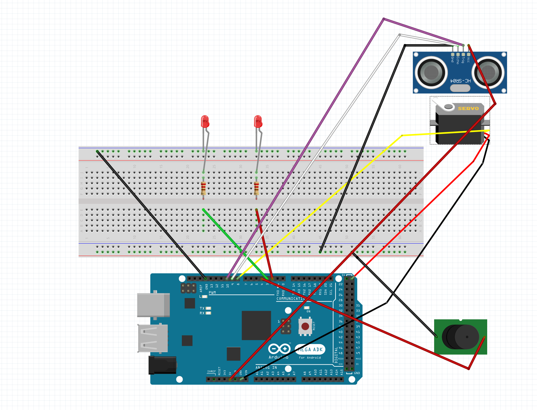
Wiring Instructions
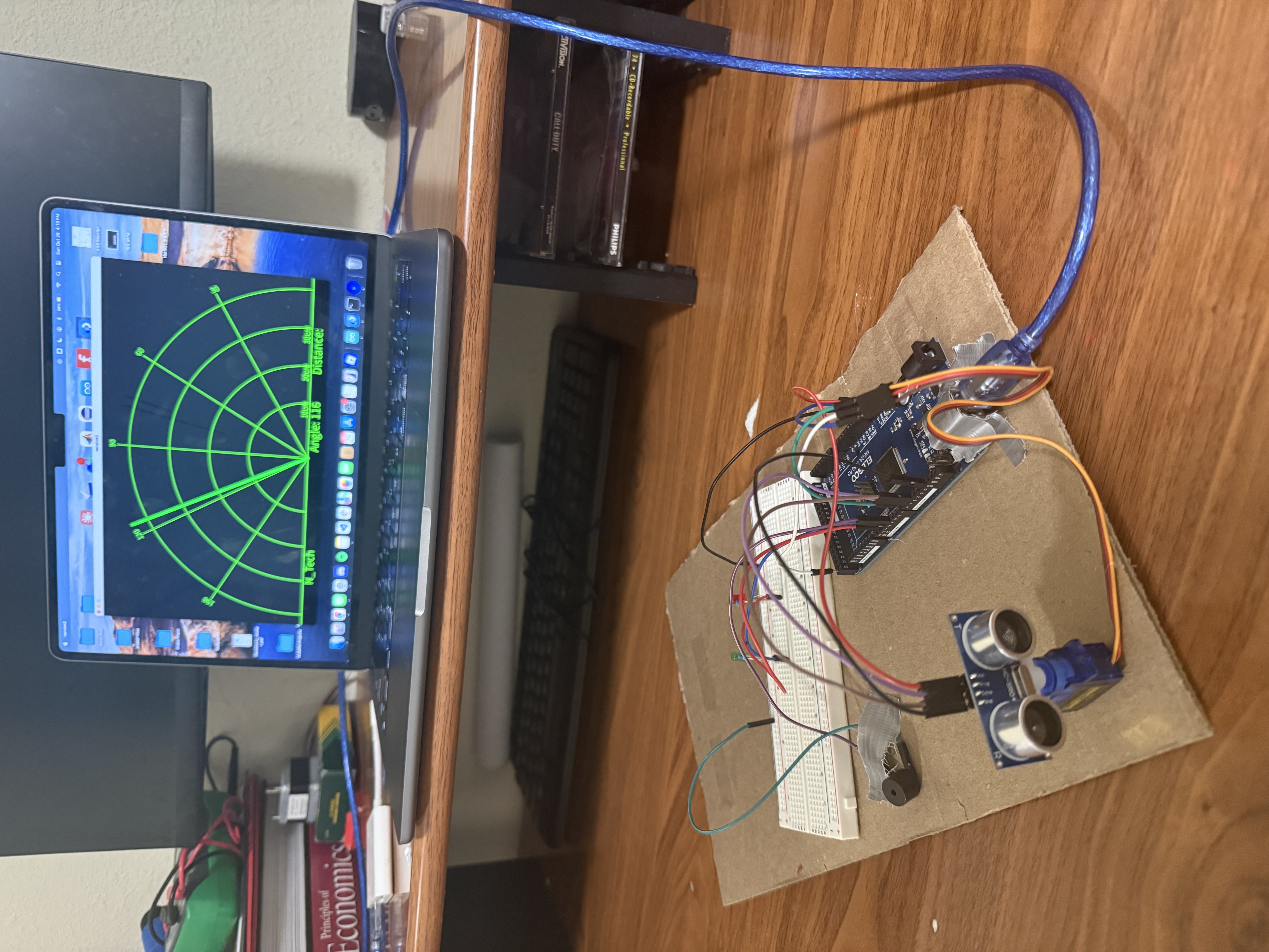
Ultrasonic Sensor (HC-SR04): TRIG = Pin 9, ECHO = Pin 10, VCC = 5V, GND = GND
Servo Motor: Signal = Pin 8, VCC = 5V, GND = GND
Red LED: Pin 2 (through 220Ω resistor)
Green LED: Pin 3 (through 220Ω resistor)
Buzzer: Pin 4, GND = GND
Project Photos & Demo
Arduino Code (Hardware Control)
This code runs on the Arduino to control the servo sweeping motion, ultrasonic distance measurement, and LED/buzzer feedback based on object detection.
#include <Servo.h>

#define trigPin 9
#define echoPin 10
#define redLed 2
#define greenLed 3
#define buzzer 4

Servo myservo;

long duration;
int distance;
unsigned long previousMillis = 0;

bool lockedOn = false;
int servoAngle = 25;
int sweepDir = 1; // 1 = forward, -1 = backward
int ledState = LOW;
int buzzerState = LOW;

int calculateDistance() {
  digitalWrite(trigPin, LOW);
  delayMicroseconds(2);
  digitalWrite(trigPin, HIGH);
  delayMicroseconds(10);
  digitalWrite(trigPin, LOW);
  duration = pulseIn(echoPin, HIGH);
  distance = duration * 0.034 / 2; // convert to cm

  if (distance > 30) distance = 0; // ignore farther objects
  return distance;
}

void setup() {
  pinMode(trigPin, OUTPUT);
  pinMode(echoPin, INPUT);
  pinMode(redLed, OUTPUT);
  pinMode(greenLed, OUTPUT);
  pinMode(buzzer, OUTPUT);
  myservo.attach(8);
  myservo.write(servoAngle);
  Serial.begin(9600);
}

void loop() {
  int dist = calculateDistance();

  // ---------- Lock-on / Resume logic ----------
  if (dist > 0) {
    // Object detected → stop scanning
    lockedOn = true;
  } else {
    // No object → resume scanning
    lockedOn = false;
  }

  if (!lockedOn) {
    // Normal sweeping motion
    servoAngle += sweepDir;
    if (servoAngle >= 155 || servoAngle <= 25) sweepDir *= -1;
    myservo.write(servoAngle);
  } else {
    // Stay fixed while object is detected
    myservo.write(servoAngle);
  }

  blinkLEDandBuzzer(dist, lockedOn);

  // ---------- Serial output ----------
  Serial.print(servoAngle);
  Serial.print(",");
  Serial.print(dist);
  Serial.print(".");
  delay(15);
}

// -------------------------------------------------
// LED + buzzer behavior
// -------------------------------------------------
void blinkLEDandBuzzer(int dist, bool locked) {
  unsigned long currentMillis = millis();
  int blinkInterval;

  if (!locked) {
    // Nothing detected → Green blinking slowly, red/buzzer off
    blinkInterval = 1000;
    digitalWrite(greenLed, (currentMillis / 500) % 2);
    digitalWrite(redLed, LOW);
    digitalWrite(buzzer, LOW);
  } else {
    // Object detected → Red LED + buzzer blink fast
    blinkInterval = 200; // fast blink
    if (currentMillis - previousMillis >= blinkInterval / 2) {
      previousMillis = currentMillis;
      ledState = !ledState;
      buzzerState = !buzzerState;
      digitalWrite(redLed, ledState);
      digitalWrite(greenLed, LOW);
      digitalWrite(buzzer, buzzerState);
    }
  }
}
Processing Code (Visual Radar Display)
This Processing code receives angle and distance data from the Arduino via serial communication and renders a real-time radar visualization showing detected objects.
import processing.serial.*; // imports library for serial communication
import java.awt.event.KeyEvent; // imports library for reading the data from the serial port
import java.io.IOException;
Serial myPort; // defines Object Serial
// defines variables
String angle="";
String distance="";
String data="";
String noObject;
float pixsDistance;
int iAngle, iDistance;
int index1=0;
int index2=0;
PFont orcFont;

void setup() {
  size (1200, 700); // ***CHANGE THIS TO YOUR SCREEN RESOLUTION***
  smooth();
  myPort = new Serial(this, "Port Name", 9600); // starts the serial communication
  myPort.bufferUntil('.'); // reads the data from the serial port up to the character '.'
}

void draw() {
  fill(98, 245, 31);
  // simulating motion blur and slow fade of the moving line
  noStroke();
  fill(0, 4);
  rect(0, 0, width, height-height*0.065);

  fill(98, 245, 31); // green color
  // calls the functions for drawing the radar
  drawRadar();
  drawLine();
  drawObject();
  drawText();
}

void serialEvent (Serial myPort) {
  data = myPort.readStringUntil('.');
  data = data.substring(0, data.length()-1);

  index1 = data.indexOf(",");
  angle= data.substring(0, index1);
  distance= data.substring(index1+1, data.length());

  iAngle = int(angle);
  iDistance = int(distance);
}

void drawRadar() {
  pushMatrix();
  translate(width/2, height-height*0.074);
  noFill();
  strokeWeight(2);
  stroke(98, 245, 31);
  arc(0, 0, (width-width*0.0625), (width-width*0.0625), PI, TWO_PI);
  arc(0, 0, (width-width*0.27), (width-width*0.27), PI, TWO_PI);
  arc(0, 0, (width-width*0.479), (width-width*0.479), PI, TWO_PI);
  arc(0, 0, (width-width*0.687), (width-width*0.687), PI, TWO_PI);
  line(-width/2, 0, width/2, 0);
  line(0, 0, (-width/2)*cos(radians(30)), (-width/2)*sin(radians(30)));
  line(0, 0, (-width/2)*cos(radians(60)), (-width/2)*sin(radians(60)));
  line(0, 0, (-width/2)*cos(radians(90)), (-width/2)*sin(radians(90)));
  line(0, 0, (-width/2)*cos(radians(120)), (-width/2)*sin(radians(120)));
  line(0, 0, (-width/2)*cos(radians(150)), (-width/2)*sin(radians(150)));
  line((-width/2)*cos(radians(30)), 0, width/2, 0);
  popMatrix();
}

void drawObject() {
  pushMatrix();
  translate(width/2, height-height*0.074);
  strokeWeight(9);
  stroke(255, 10, 10);

  // Adjusted scale to 30 cm max range
  pixsDistance = iDistance * ((height - height * 0.1666) * 0.03);

  // Limit the visual range to 30 cm
  if (iDistance < 30 && iDistance > 0) {
    line(pixsDistance * cos(radians(iAngle)),
         -pixsDistance * sin(radians(iAngle)),
         (width - width * 0.505) * cos(radians(iAngle)),
         -(width - width * 0.505) * sin(radians(iAngle)));
  }
  popMatrix();
}

void drawLine() {
  pushMatrix();
  strokeWeight(9);
  stroke(30, 250, 60);
  translate(width/2, height - height * 0.074);
  line(0, 0, (height - height * 0.12) * cos(radians(iAngle)),
       -(height - height * 0.12) * sin(radians(iAngle)));
  popMatrix();
}

void drawText() {
  pushMatrix();
  if (iDistance > 30 || iDistance <= 0) {
    noObject = "Out of Range";
  } else {
    noObject = "In Range";
  }

  fill(0, 0, 0);
  noStroke();
  rect(0, height - height * 0.0648, width, height);
  fill(98, 245, 31);
  textSize(25);

  text("10cm", width - width * 0.3854, height - height * 0.0833);
  text("20cm", width - width * 0.281, height - height * 0.0833);
  text("30cm", width - width * 0.177, height - height * 0.0833);
  textSize(40);
  text("N_Tech ", width - width * 0.875, height - height * 0.0277);
  text("Angle: " + iAngle + " ", width - width * 0.48, height - height * 0.0277);
  text("Distance: ", width - width * 0.26, height - height * 0.0277);

  if (iDistance < 30 && iDistance > 0) {
    text("        " + iDistance + " cm", width - width * 0.225, height - height * 0.0277);
  }

  textSize(25);
  fill(98, 245, 60);
  translate((width - width * 0.4994) + width / 2 * cos(radians(30)),
            (height - height * 0.0907) - width / 2 * sin(radians(30)));
  rotate(-radians(-60));
  text("30", 0, 0);
  resetMatrix();
  translate((width - width * 0.503) + width / 2 * cos(radians(60)),
            (height - height * 0.0888) - width / 2 * sin(radians(60)));
  rotate(-radians(-30));
  text("60", 0, 0);
  resetMatrix();
  translate((width - width * 0.507) + width / 2 * cos(radians(90)),
            (height - height * 0.0833) - width / 2 * sin(radians(90)));
  rotate(radians(0));
  text("90", 0, 0);
  resetMatrix();
  translate(width - width * 0.513 + width / 2 * cos(radians(120)),
            (height - height * 0.07129) - width / 2 * sin(radians(120)));
  rotate(radians(-30));
  text("120", 0, 0);
  resetMatrix();
  translate((width - width * 0.5104) + width / 2 * cos(radians(150)),
            (height - height * 0.0574) - width / 2 * sin(radians(150)));
  rotate(radians(-60));
  text("150", 0, 0);
  popMatrix();
}
🔧 Troubleshooting
Common issues with the servo radar system and their solutions:
- Verify HC-SR04 wiring: TRIG to Pin 9, ECHO to Pin 10, VCC to 5V, GND to GND.
- Check that objects are within 2-30cm range - sensor accuracy drops outside this range.
- Ensure the sensor is not pointed at sound-absorbing materials (fabric, foam) which don't reflect ultrasonic waves well.
- Test the sensor independently using Serial.println(distance) to verify readings before adding visualization.
Hard, flat surfaces like cardboard, plastic, or your hand work best for detection. Soft or angled surfaces may not reflect ultrasonic waves back to the sensor reliably.
- Confirm servo signal wire is connected to Pin 8, power to 5V, ground to GND.
- Check that Servo.h library is included and myservo.attach(8) is called in setup().
- If servo jitters or moves erratically, use external 5V power supply - servos can draw too much current from Arduino.
- Verify sweep range in code (25° to 155°) - adjust if needed based on your physical setup.
For stable operation, especially when adding LEDs and buzzer, consider using an external 5V supply for the servo. Keep all grounds connected together.
- Install Processing from processing.org if not already installed.
- Update "Port Name" in Processing code (line 19) to match your Arduino's serial port (check Arduino IDE → Tools → Port).
- Close Arduino Serial Monitor before running Processing - only one application can access the serial port at a time.
- Adjust screen resolution in setup() function (line 17) to match your display if visualization appears cut off.
- Verify Arduino is sending data by checking Serial Monitor first - you should see "angle,distance." format (e.g., "45,12.").
On Windows, ports are named "COM3", "COM4", etc. On Mac, they look like "/dev/cu.usbmodem14101". On Linux, "/dev/ttyUSB0" or similar. Use the exact name from Arduino IDE.
- Check LED polarity - longer leg (anode) connects to Arduino pin through resistor, shorter leg (cathode) to GND.
- Verify 220Ω resistors are used with LEDs to prevent burnout.
- Confirm pin connections: Red LED to Pin 2, Green LED to Pin 3, Buzzer to Pin 4.
- Test LEDs independently with simple blink code before integrating into radar system.
- For buzzer, ensure it's an active buzzer (has internal oscillator) - passive buzzers need PWM tone() function.
Green LED should blink slowly when no object detected, red LED and buzzer should blink rapidly when object is within 30cm range.
What You Learned
Electrical Engineering Applications
This project demonstrates ultrasonic distance measurement using time-of-flight calculations, servo motor PWM control for precise angular positioning, and real-time serial data transmission. You learned how to calculate distance from ultrasonic pulse duration (speed of sound = 343 m/s), implement sweeping scan patterns with directional logic, synchronize hardware sensors with software visualization, and manage multiple output devices (LEDs, buzzer) based on sensor feedback. The lock-on behavior when detecting objects introduces basic target tracking concepts used in radar systems.
Broader Technology Context
Radar systems are fundamental to modern technology, from aviation (air traffic control, weather radar) to automotive (parking sensors, collision avoidance, autonomous vehicles), robotics (obstacle detection, navigation), security (motion detection), and industrial automation (level sensing, proximity detection). This project introduces core concepts used in LIDAR, sonar, and radar technologies. Understanding how to visualize sensor data in real-time is critical for robotics, data acquisition systems, scientific instruments, and IoT dashboards. The Arduino-to-Processing communication pattern is widely used in embedded systems that need graphical interfaces for monitoring and control.