Temperature Controlled Fan MEDIUM
An automatic fan control system that adjusts fan speed based on ambient temperature. The system uses a temperature sensor to monitor heat and controls a DC fan accordingly.
Materials Used
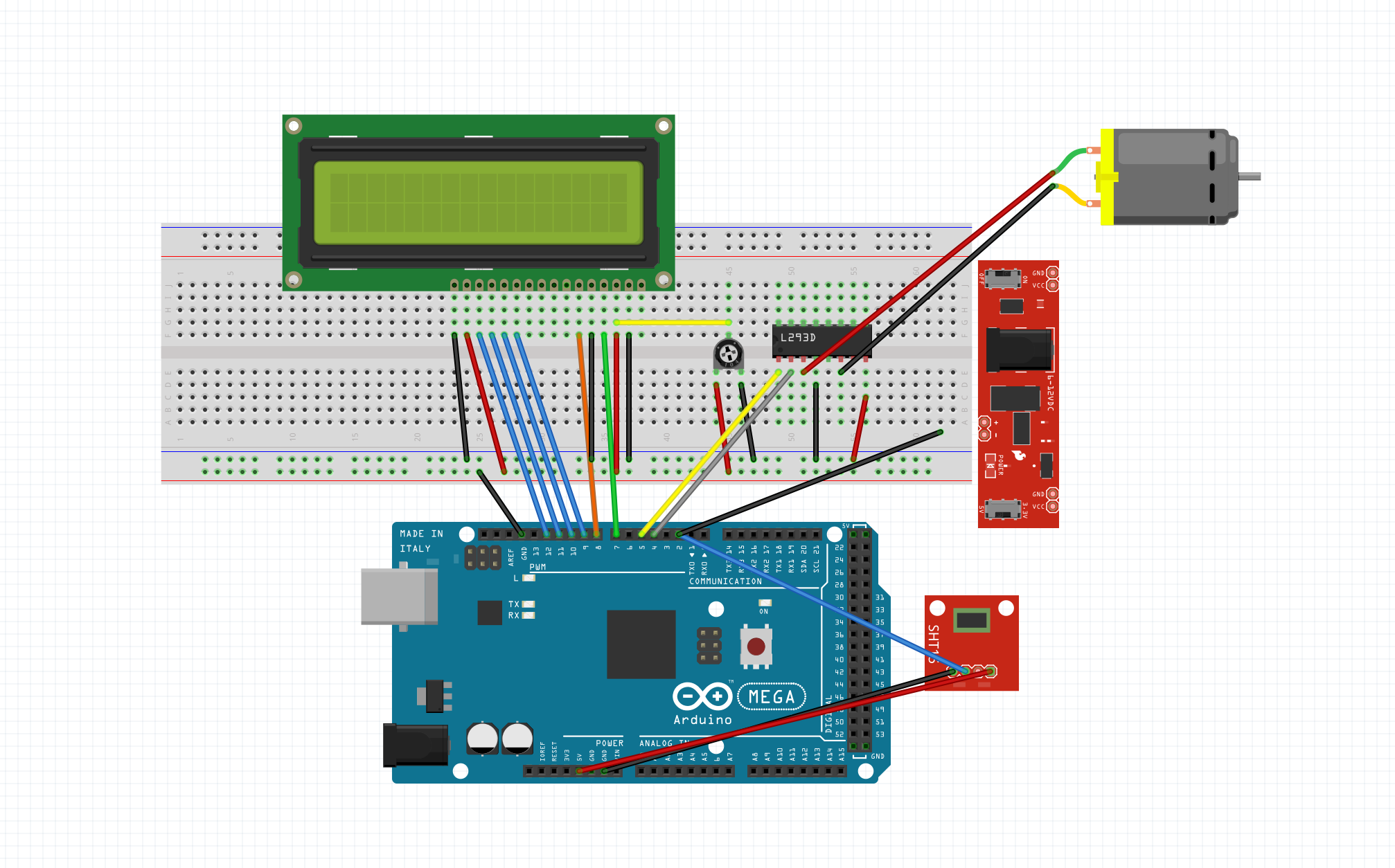
Wiring Instructions
LCD: RS=7, E=8, D4-D7=9-12, GND=RW/VSS, 5V=VCC
DHT22: DATA=Pin 2, VCC=5V, GND=GND
L293D Motor: IN1=3, IN2=4, EN1=5 (PWM), Vcc1=5V, Vcc2=5V (motor supply)
Note: All grounds (Arduino + Power Supply + L293D) must be connected together
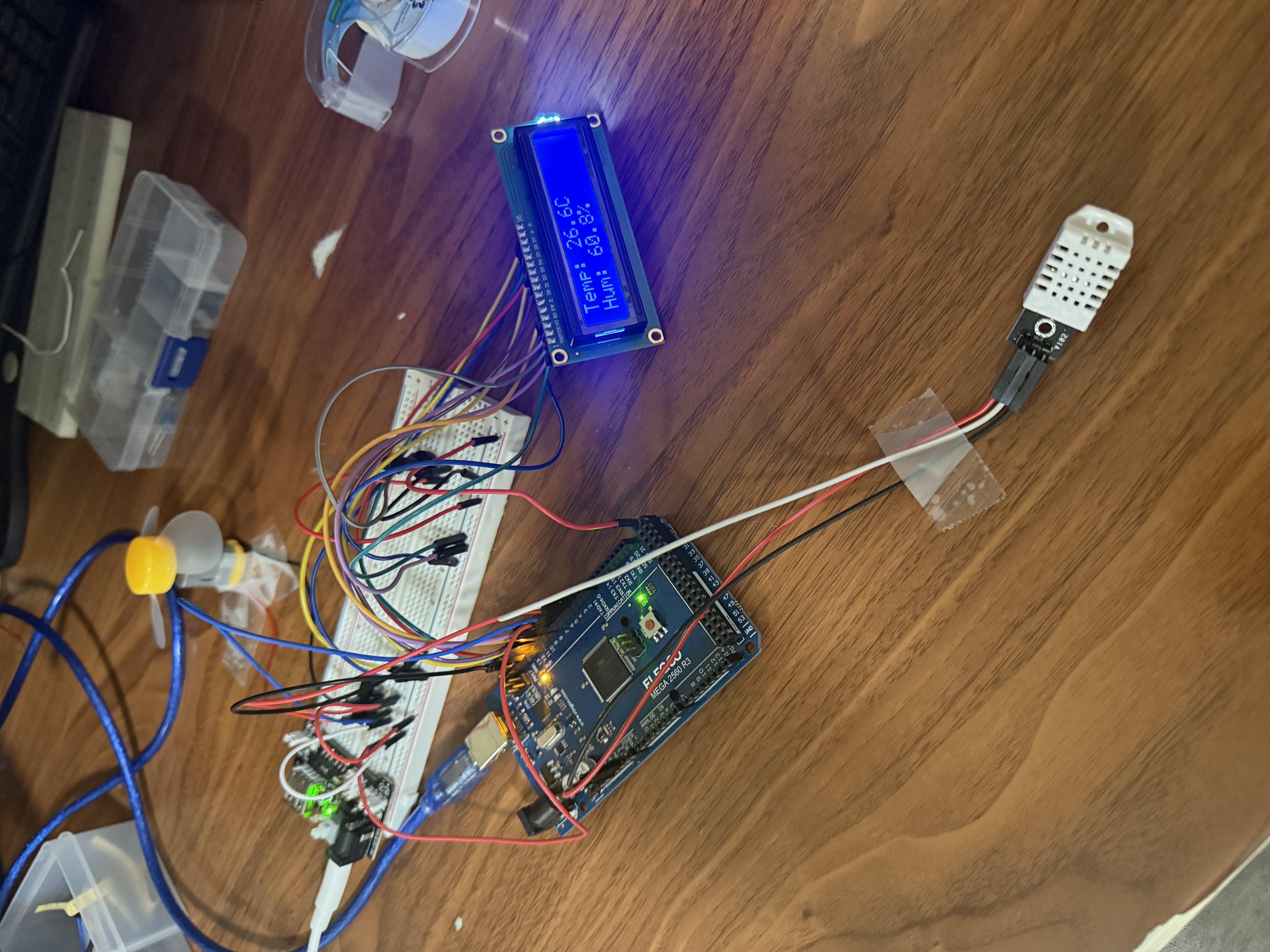
Project Photos & Demo
Arduino Code
// Temperature Controlled Fan
const int tempPin = A0;
const int fanPin = 9;

void setup() {
  pinMode(fanPin, OUTPUT);
  Serial.begin(9600);
}

void loop() {
  int tempReading = analogRead(tempPin);
  float voltage = tempReading * (5.0 / 1023.0);
  float temperatureC = voltage * 100;

  Serial.print("Temperature: ");
  Serial.print(temperatureC);
  Serial.println(" C");

  int fanSpeed = 0;

  if (temperatureC < 25) {
    fanSpeed = 0;
  } else if (temperatureC < 30) {
    fanSpeed = 128;
  } else if (temperatureC < 35) {
    fanSpeed = 192;
  } else {
    fanSpeed = 255;
  }

  analogWrite(fanPin, fanSpeed);

  Serial.print("Fan Speed: ");
  Serial.println(fanSpeed);

  delay(1000);
}
🔧 Troubleshooting
Fan not responding to temperature? Check these solutions:
- Verify DHT22 connections: DATA→Pin 2, VCC→5V, GND→GND.
- Install DHT sensor library: Sketch → Include Library → Manage Libraries → search "DHT sensor library".
- Check Serial Monitor output - if showing "Failed to read", sensor may be damaged or incorrectly wired.
- Ensure DHT sensor has proper pull-up resistor (4.7-10kΩ between DATA and VCC) - some modules have built-in resistors.
DHT11 and DHT22 have different accuracy and pin configurations. Make sure DHTTYPE in code matches your physical sensor!
- Check L293D motor driver connections: IN1→Pin 3, IN2→Pin 4, EN1→Pin 5 (PWM), both Vcc pins→5V.
- Ensure all grounds connected: Arduino GND, L293D GND, power supply GND must be common.
- Verify motor power supply (Vcc2 on L293D) is adequate - try external 5-9V supply.
- Test motor directly with 3-5V to confirm it works before debugging circuit.
All grounds MUST be connected together. This is the #1 reason motor drivers fail. Check with multimeter that all GND points have continuity.
- Verify PWM pin (Pin 5) is being used - only certain Arduino pins support analogWrite().
- Check temperature thresholds in code - adjust values to match your testing environment.
- Use Serial.println() to debug temperature readings and fanSpeed values in real-time.
- Ensure analogWrite() is called with correct pin and 0-255 value range.
Lower temperature thresholds to 20/25/30°C for easier testing. Or gently warm the sensor with your hand to trigger speed changes.
What You Learned
Electrical Engineering Applications
This project demonstrates closed-loop feedback control systems, where sensor input directly influences actuator output. You learned about analog temperature sensing, PWM (Pulse Width Modulation) for motor speed control, voltage-to-temperature conversion, threshold-based control logic, and motor driver ICs for current amplification. These concepts are foundational in thermal management, power electronics, and automated control systems used throughout electrical engineering.
Broader Technology Context
Temperature-controlled fan systems are critical in computer cooling (CPU/GPU thermal management), HVAC systems, automotive engine cooling, data center climate control, industrial process control, and battery thermal management in electric vehicles. This feedback control architecture extends to thermostats, refrigeration systems, incubators, and any application requiring automatic temperature regulation. Understanding proportional control prepares you for advanced PID control in industrial automation.