Adjustable Fan MEDIUM
A versatile fan control system that allows you to adjust both the direction and speed of a fan using a rotary encoder. Control fan angle with servo motor rotation and switch between OFF, MEDIUM, and FAST speeds with a button press.
Materials Used
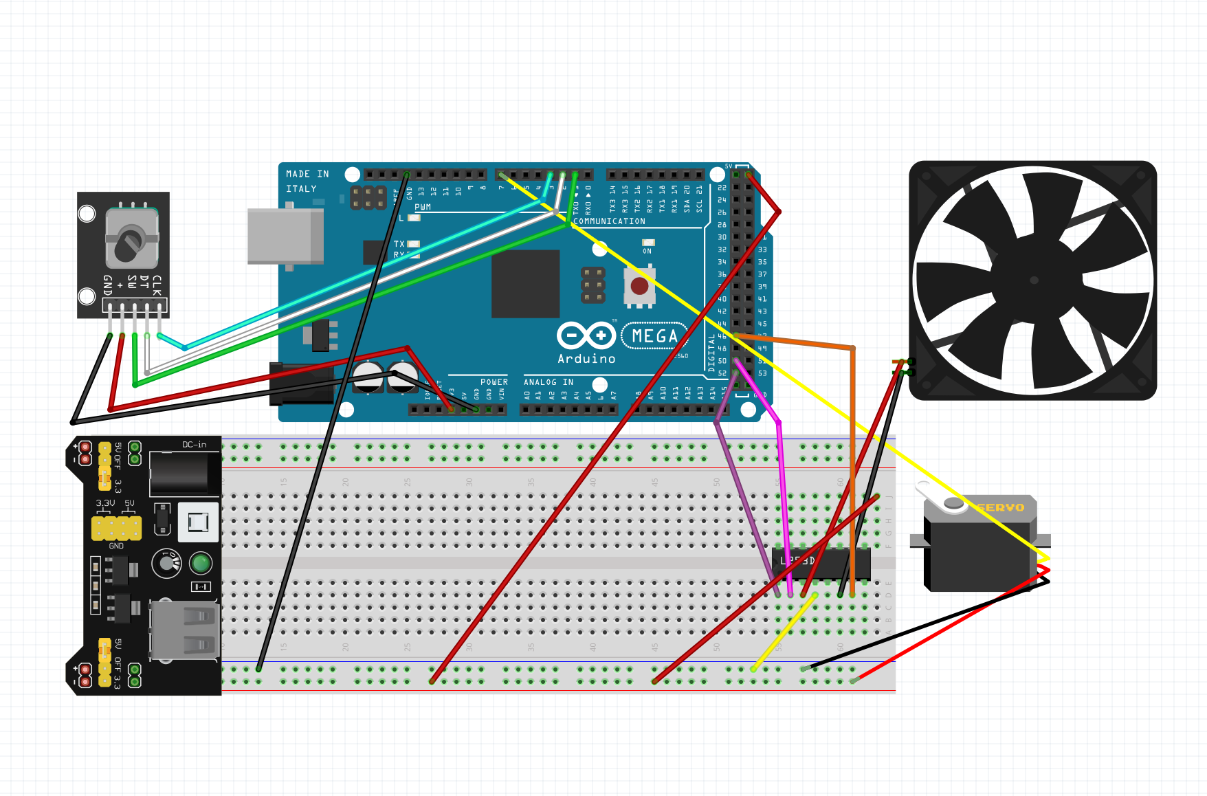
Wiring Instructions
Rotary Encoder Connections:
• CLK → Pin 3
• DT → Pin 2
• SW (button) → Pin 1
• + → 5V
• GND → GND
Servo Motor Connections:
• Signal (Orange/Yellow) → Pin 7
• Power (Red) → 5V
• Ground (Brown/Black) → GND
L293D Motor Driver Connections:
• ENABLE → Pin 52 (PWM)
• INPUT 1 (DIRA) → Pin 50
• INPUT 2 (DIRB) → Pin 46
• OUTPUT 1 & 2 → DC Fan Motor
• VCC1 → 5V (logic power)
• VCC2 → External Power Supply (motor power)
• GND → GND (both logic and motor grounds)
Circuit Diagram
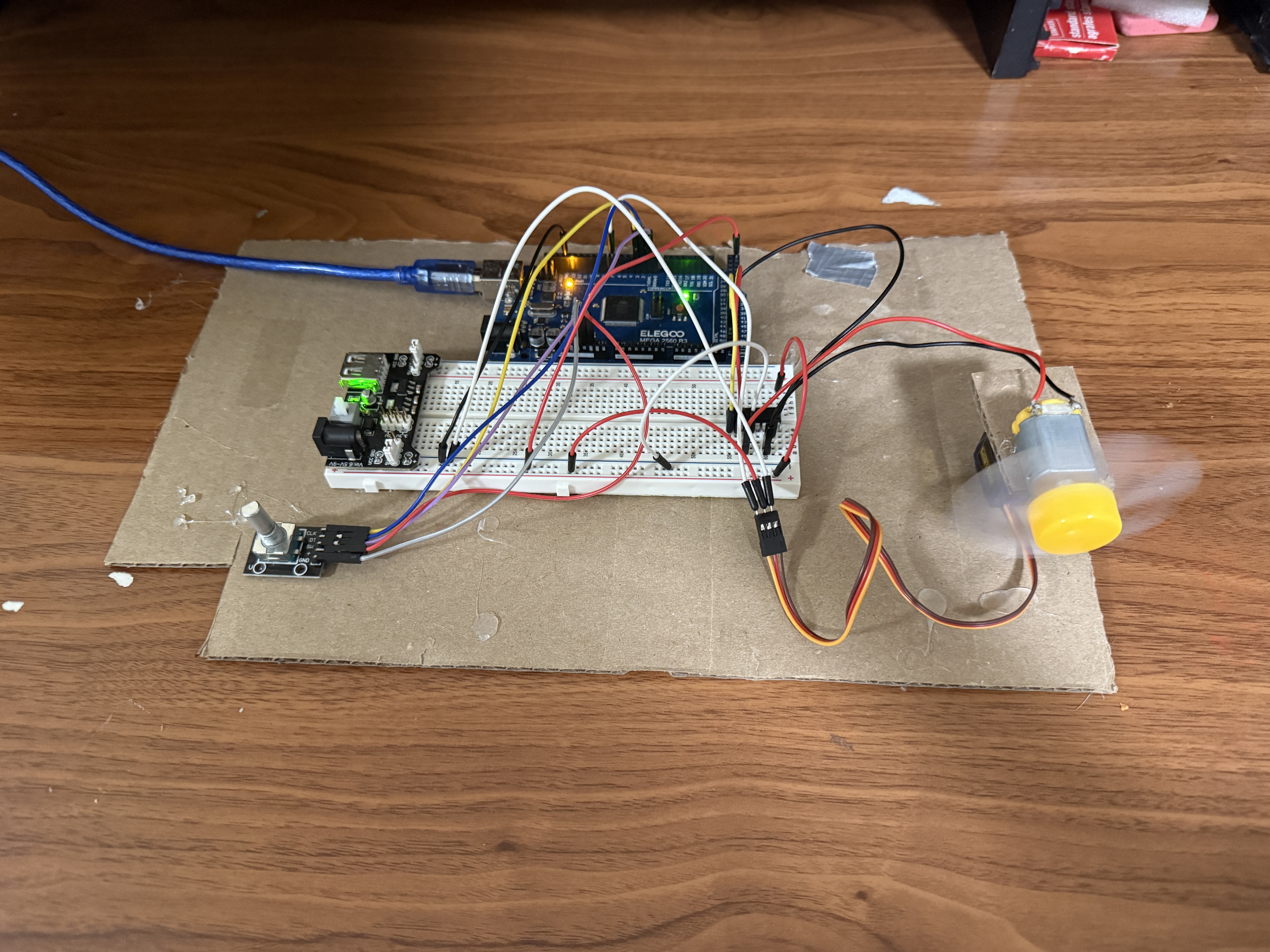
Project Photos & Demo
Arduino Code
#include <Servo.h>

Servo servo;

// ===== Rotary Encoder Pins =====
const int clkPin = 3;
const int dtPin  = 2;
const int swPin  = 1;

// ===== Servo =====
const int servoPin = 7;
int angle = 90;
const int stepSize = 10;
int lastClk;

// ===== L293D Motor Driver =====
const int ENABLE = 52;
const int DIRA   = 50;
const int DIRB   = 46;

// ===== Fan Control =====
int mode = 0;  // 0 = OFF, 1 = MEDIUM, 2 = FAST

// ===== PWM Levels =====
const int KICK_POWER = 255;
const int MEDIUM_POWER = 170;
const int FAST_POWER = 255;

void setup() {
  // Servo
  servo.attach(servoPin);
  servo.write(angle);

  // Encoder
  pinMode(clkPin, INPUT);
  pinMode(dtPin, INPUT);
  pinMode(swPin, INPUT_PULLUP);
  lastClk = digitalRead(clkPin);

  // Motor driver
  pinMode(ENABLE, OUTPUT);
  pinMode(DIRA, OUTPUT);
  pinMode(DIRB, OUTPUT);

  // Fixed direction
  digitalWrite(DIRA, HIGH);
  digitalWrite(DIRB, LOW);

  analogWrite(ENABLE, 0);  // fan off
}

void loop() {

  handleEncoder();
  handleFanButton();

}

// ===== ROTARY ENCODER → SERVO =====
void handleEncoder() {
  int currentClk = digitalRead(clkPin);

  if (currentClk != lastClk && currentClk == HIGH) {
    if (digitalRead(dtPin) == currentClk) {
      angle += stepSize;
    } else {
      angle -= stepSize;
    }

    angle = constrain(angle, 0, 180);
    servo.write(angle);
  }

  lastClk = currentClk;
}

// ===== BUTTON → FAN MODE =====
void handleFanButton() {
  if (digitalRead(swPin) == LOW) {
    delay(150);  // debounce

    mode++;
    if (mode > 2) mode = 0;

    switch (mode) {

      case 0:
        // OFF
        analogWrite(ENABLE, 0);
        break;

      case 1:
        // MEDIUM with aggressive jumpstart
        analogWrite(ENABLE, KICK_POWER);
        delay(1000);              // longer kick
        analogWrite(ENABLE, 0);
        delay(50);                // brief drop
        analogWrite(ENABLE, KICK_POWER);
        delay(500);
        analogWrite(ENABLE, MEDIUM_POWER);
        break;

      case 2:
        // FAST (full power)
        analogWrite(ENABLE, FAST_POWER);
        break;
    }

    // wait for button release
    while (digitalRead(swPin) == LOW);
    delay(150);
  }
}
🔧 Troubleshooting
Having issues with your circuit? Check these common problems and solutions:
- Check external power supply is connected to VCC2 on L293D - Arduino 5V alone may not provide enough current.
- Verify L293D ENABLE pin (52) is receiving PWM signal - measure with multimeter when fan should be on.
- Confirm DIRA and DIRB are set correctly (one HIGH, one LOW) for motor direction.
- Test fan motor directly with external power to ensure it's not damaged.
- Check all GND connections are common between Arduino, L293D, and external power.
DC motors require kickstart power to overcome inertia. The code uses 255 PWM briefly before dropping to medium speed (170). If fan still won't start, try increasing KICK_POWER duration.
- Verify servo is connected to pin 7 (signal), 5V (power), and GND.
- Check rotary encoder CLK (pin 3) and DT (pin 2) connections - they detect rotation direction.
- Test encoder by adding Serial.println(angle) in handleEncoder() to see if values change.
- Ensure servo has sufficient power - consider using external 5V supply if Arduino voltage drops.
- Verify Servo library is included and servo.attach() is called in setup().
Encoder rotation should change angle by stepSize (10°). Try rotating slowly and observe servo movement. If erratic, add small delay or increase debouncing.
- Check encoder button (SW) is connected to pin 1 with INPUT_PULLUP enabled.
- Verify button press reads LOW when pressed - INPUT_PULLUP makes it normally HIGH.
- Ensure mode variable cycles correctly: 0 (OFF) → 1 (MEDIUM) → 2 (FAST) → 0.
- Add Serial.println(mode) in handleFanButton() to debug mode transitions.
- Check debounce delays (150ms) are sufficient - increase if button triggers multiple times.
The code waits for button release with while loop. If stuck, button might be registering as always pressed - check wiring and pull-up resistor.
- Add capacitor (100µF) across servo power and ground to stabilize voltage.
- Use external 5V power for servo instead of Arduino 5V pin - servos draw high current.
- Keep servo wires short and away from motor wires to reduce electromagnetic interference.
- Add small delay after servo.write() to allow servo time to reach position.
- Check angle updates aren't too frequent - encoder may be sending rapid changes.
Servo jitter often indicates power supply issues. When motor runs at high speed, it can cause voltage drops affecting servo. Use separate power rails or add filtering capacitors.
- Verify ENABLE pin (52) is PWM-capable - check Arduino Mega pinout.
- Confirm analogWrite() values differ between modes: 0 (OFF), 170 (MEDIUM), 255 (FAST).
- Check L293D enable pin is connected to Arduino PWM pin, not digital-only pin.
- Test by manually setting analogWrite(ENABLE, 128) in loop - should run at half speed.
- Ensure motor can actually vary speed - some motors need minimum voltage to run.
The kickstart sequence (full power → brief stop → full power → reduced speed) helps overcome motor inertia at medium speed. Adjust MEDIUM_POWER (170) if fan is too slow or fast.
What You Learned
Electrical Engineering Applications
This project demonstrates advanced motor control techniques using PWM (Pulse Width Modulation) for speed regulation and H-bridge circuitry (L293D) for direction control. You learned about rotary encoder quadrature signals for detecting rotation direction, servo motor control using PWM signals, and the importance of kickstart sequences to overcome motor inertia. The project also covers power supply considerations, including separate logic and motor power domains, and the relationship between duty cycle and motor speed.
Broader Technology Context
Multi-input motor control systems like this are fundamental to robotics, HVAC systems, and automated manufacturing. Rotary encoders are used in everything from volume knobs on audio equipment to precision positioning in CNC machines and 3D printers. PWM speed control is essential in electric vehicles, drone propulsion, and industrial automation. The combination of directional control (servo) and speed control (PWM) mirrors real-world applications like automated camera gimbals, solar panel tracking systems, and smart home ventilation. Understanding these principles is crucial for developing IoT devices, robotic systems, and any application requiring precise motor control.